|
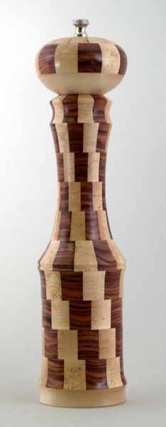 |
Segmented Ring Peppermill Construction
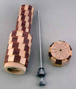
This is a brief description of how I construct peppermills such as the
one shown in this photo. This is a 12" tall peppermill,
constructed of 158 separate pieces of wood. The techniques can easily be
modified to other sized peppermills.
The mechanical parts that I use require a 1 1/16" diameter
recess in the base of the mill to accommodate the grinding mechanism. I
also add a 2" diameter recess about 1/2" deep in the base to
allow for clearance of the grinder mechanism. I sign and number the
piece inside this recess.
The top knob has a spigot about 1/4" long and 1" in
diameter, that fits into a corresponding 1" diameter hole in the
top of the mill body. The rest of the body is drilled out to 3/4".
(The whole body could be drilled out at 1" or even 1 1/16" to
simplify construction, but I like the extra wood thickness at the
narrow point of the neck.)
The mechanical parts I use measure 11 7/8" from the base to the
top of the threaded shaft, with 5/8" of threading on the shaft. The
total height from the 2" recess in the base to the top of the knob
has to be around 11 1/2". My design gets close to this by
construction, then I adjust the final height when I turn to knob by
adjusting the thickness of the solid piece at the base of the knob.
I use Titebond carpenters glue for all my work. It's easy to work
with, inexpensive, cleans up with water, and sets relatively quickly. |
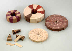
Constructing the Rings
I start by milling the wood I will be using to a standard width and
thickness. I plane the wood to just under 1" thick - about
15/16". This thickness has evolved primarily because I tend to use
1" rough lumber which is sometimes hard to keep at 1" when
planeing. I use two widths - 1 1/4" for the 5 lower rings, and
3/4" for the upper rings. This again has evolved - the smaller
rings in the upper neck can allow me to make more efficient use of the
lumber.
For the 12" mill, I use 6 small rings - about 2" in
diameter, 6 wide rings - about 3 1/4" diameter, a
3/8" thick 'starburst' top ring, and two solid pieces of wood for
the base and bottom of the knob.
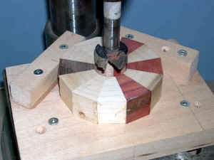
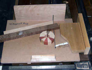 I cut the segments for each ring on a table saw with the jig shown
here. The jig has been carefully calibrated to cut at exactly 15
degrees so that when assembled, the rings have no gaps. I cut the segments for each ring on a table saw with the jig shown
here. The jig has been carefully calibrated to cut at exactly 15
degrees so that when assembled, the rings have no gaps.
(As an aside, I always use the tablesaw with the blade at 90 degrees
- never tilted. I build jigs that tilt the lumber when necessary. I use
an accurate square to set the blade at 90, and leave it locked. If the
cut is slightly off 90, the rings will not go together correctly.)
|
 The rings are then glued together. I always clamp the rings with
metal hose clamps to squeeze all the glue I can out of the joints. The
best setup is actually to use two shorter clamps linked end-to-end. This
gives you two screws to tighten with. The rings are then glued together. I always clamp the rings with
metal hose clamps to squeeze all the glue I can out of the joints. The
best setup is actually to use two shorter clamps linked end-to-end. This
gives you two screws to tighten with. |
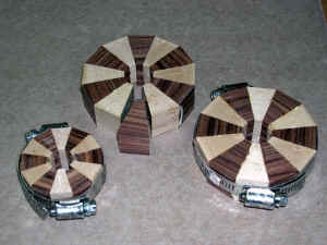
 Here
are some examples of assembled rings. The two thicker rings are
used for the body of the peppermill, the thinner ones are for the
'starburst' top I put on many of the mills. The starburst is created by
inserting pieces of veneer between the segments that make up the ring.
These rings are a bit trickier to glue up - they have more pieces to
glue, and the center hole has to be less than 1/4". I usually first
glue a strip of veneer to each segments, then glue the segments
together. (Hint - unless you require solid wood right to the center,
always leave at least a small hole in the center. The gluing and
clamping is a lot easier!) Here
are some examples of assembled rings. The two thicker rings are
used for the body of the peppermill, the thinner ones are for the
'starburst' top I put on many of the mills. The starburst is created by
inserting pieces of veneer between the segments that make up the ring.
These rings are a bit trickier to glue up - they have more pieces to
glue, and the center hole has to be less than 1/4". I usually first
glue a strip of veneer to each segments, then glue the segments
together. (Hint - unless you require solid wood right to the center,
always leave at least a small hole in the center. The gluing and
clamping is a lot easier!) |
Sanding and Drilling
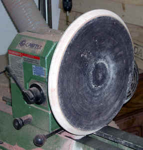 Once I've glued all the rings, I give them a quick sanding on a disk
sander to get rid of any small imperfections. My disk sander is a
shop-built disk that mounts onto one of my lathes. I use a 12" disk of
fairly coarse sandpaper - 100 - 150 grit. It is mounted on an MDF disk
that's attached to a faceplate.I have a make-shift hood that
goes over the whole thing to try and pick up as much dust as possible -
it generates plenty! The photo on the right shows the disk. Once I've glued all the rings, I give them a quick sanding on a disk
sander to get rid of any small imperfections. My disk sander is a
shop-built disk that mounts onto one of my lathes. I use a 12" disk of
fairly coarse sandpaper - 100 - 150 grit. It is mounted on an MDF disk
that's attached to a faceplate.I have a make-shift hood that
goes over the whole thing to try and pick up as much dust as possible -
it generates plenty! The photo on the right shows the disk.
There are two tricky parts to sanding the rings. #1 - avoid sanding
your fingers! #2 - avoid sanding the ring more on one side than the
other. Normally one holds the ring between the edge and middle of
the sanding disk. Since the outer sanding area is moving faster, it
sands more off of that side of the ring. I find that it helps to rotate the ring as
you're holding it against the sanding disk, so that any inconsistencies
are balanced out.
|
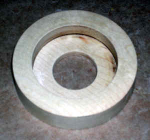
 Next I drill out the center of each ring. I use
a drill press to drill the centers out to 7/8", then drill the ring
for the top of the neck to 1" diameter to a depth of about 1/2". The
ring to go on the bottom of the mill is drilled to 1 1/16"diameter
about 5/8" (the depth of the grinder mechanism.) Actually,
this ring will be second-to-bottom, as a solid ring is added later (see
below). Next I drill out the center of each ring. I use
a drill press to drill the centers out to 7/8", then drill the ring
for the top of the neck to 1" diameter to a depth of about 1/2". The
ring to go on the bottom of the mill is drilled to 1 1/16"diameter
about 5/8" (the depth of the grinder mechanism.) Actually,
this ring will be second-to-bottom, as a solid ring is added later (see
below). |
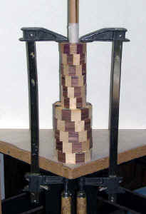 Gluing the Peppermill Body Gluing the Peppermill Body
Once the individual rings have been drilled, I assemble the body section. I use a piece of 3/4" dowel wrapped in a layer of waxed
paper as a spindle to keep all the rings precisely aligned. When the 10
rings that form the body of the mill are all glued and correctly
aligned, I clamp the whole assembly down to a workbench surface to
ensure tight glue joints between the layers. Once the assembly is
clamped to the table I pull the dowel out of the center. (Note -
the topmost ring in the photo is not actually part of the mill - it's a
clamping block I use for this step. Really just an spare ring that I use
for the job, with an extra large hole drilled in it. ) |
Solid Base
The
final piece is the solid base section. At this point I usually check the
overall height of the body of the peppermill and the amount of wood
available on the top knob assembly (allowing for 1/8"-1/4"
spigot on the knob which goes into the peppermill body). The base piece
is adjusted in thickness to get the correct total height for the
peppermill mechanism. I try to get the base section about 10" tall,
which allows some final adjustment on the 2" knob so that
everything falls within the tolerances of the mechanical parts.
 I have a small faceplate with a waste glue block
attached to it. I glue a 3 1/4" diameter piece of 3/4"-1"
wood to this with a layer of paper
between the waste block and the wood. (A quick sanding with the disk
sander will ensure that the wood is flat before gluing). When this is dry, I turn the base
piece, adjusting it's thickness to match the accumulated size of all the
rings. I bore a 2" diameter hole about 1/2" into the base
block, then bore at 1 1/16" the rest of the way through. (This
final hole matches the 1 1/16" hole that was pre-drilled in the
bottom ring). At this point I sand the sides of the 2" hole - since
it will not be accessible in later steps. This piece can be easily removed from the glue block with
a mallet and chisel, lightly sanded to remove the paper and glue, then
glued to the base. I have a small faceplate with a waste glue block
attached to it. I glue a 3 1/4" diameter piece of 3/4"-1"
wood to this with a layer of paper
between the waste block and the wood. (A quick sanding with the disk
sander will ensure that the wood is flat before gluing). When this is dry, I turn the base
piece, adjusting it's thickness to match the accumulated size of all the
rings. I bore a 2" diameter hole about 1/2" into the base
block, then bore at 1 1/16" the rest of the way through. (This
final hole matches the 1 1/16" hole that was pre-drilled in the
bottom ring). At this point I sand the sides of the 2" hole - since
it will not be accessible in later steps. This piece can be easily removed from the glue block with
a mallet and chisel, lightly sanded to remove the paper and glue, then
glued to the base.
|
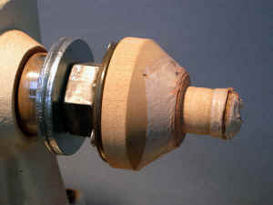
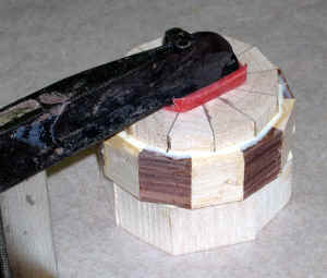 Top Knob Top Knob
The top
knob is glued up with the starburst piece on top, and a solid
piece below. This too is clamped to the workbench until the glue sets. I
usually use a 1" thick solid piece, so the resulting assembly is
about 2 3/8" top-to-bottom. The mechanical parts can now be
test-installed into the base in order to measure exactly how tall the
knob should be. An additional 3/16"-1/4" spigot is also
required, which gets inserted into the neck of the peppermill body.
|
 Ready
for Turning Ready
for Turning
This photo shows the completed base and knob assemblies ready for
final turning and assembly. |
 Turning the Peppermill Body Turning the Peppermill Body
I do all the turning by mounting the body assembly between centers. I
Have a custom built spigot chuck mounted on a small faceplate. This
allows me to drive the assembly with a 7/8" dowel inserted into the
top (neck) of the peppermill body. Some tweaking of the diameters and
tapering of this 'drive' (including some masking tape wrapped around the
dowel) enables it to slide into the 1" diameter hole in the top of
the assembly, but stop where the 7/8" inner hole begins. The beauty
of this drive arrangement is that I can get tools and sandpaper at the
top of the neck.
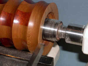 I use a standard tapered tailstock into the base. This rests nicely
in the 1 1/16" hole in the center of the base, and again, allows me
to turn and sand the base rim. I use a standard tapered tailstock into the base. This rests nicely
in the 1 1/16" hole in the center of the base, and again, allows me
to turn and sand the base rim.
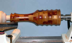
Turning the body shape is a matter of personal taste and preference.
I like to keep the lower part between 2 3/4" and 3" in
diameter, and bring the neck down to 1 1/2" or maybe a bit less.
Two critical areas are the ends - the top of the neck and base. I have a
1/4" beading tool that I use to clean up both of these. I taper the
base slightly towards the center so that the mill will rest on the
outermost rim only (for stability). At the neck I do the same
thing. I also aim for a neck rim width of 1/8"-3/16". This has
to later be matched to the base of the top knob. |
|
|
 Turning
the Top Knob Turning
the Top Knob
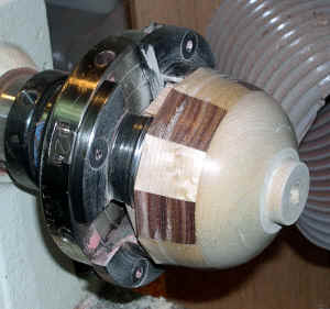
I
turn the knob by first mounting the assembly in a scroll chuck (I have a
oneway). I hold onto the starburst assembly. The middle segmented ring
is slightly larger than the starburst, so there's a convenient shoulder
to rest in the chuck against. I can then turn the lower half of the knob, adjust
the height, create the spigot, and drill the center hole. (I drill the
spigot end out to about 5/16", and the hole through the very top to
1/4".) 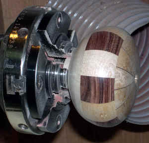 Once this is
done and sanded, I reverse the knob, holding it by the spigot in the
small jaws of a oneway chuck. Since this is a bit precarious, I
bring up the tailstock to hold things securely. (There's now a hole in
the top so it's easy to align everything.) The top is turned and sanded. Once this is
done and sanded, I reverse the knob, holding it by the spigot in the
small jaws of a oneway chuck. Since this is a bit precarious, I
bring up the tailstock to hold things securely. (There's now a hole in
the top so it's easy to align everything.) The top is turned and sanded. |
| Now
all that's left to do is apply a finish to the pieces and assemble the
mechanical parts. |
|